So my current project (outside of massive amounts of school work) is building a large, bright, RGB LED display for my college’s weekend-long end-of-year party. I’ve got three of these strips from DealExtreme, which have 30 RGB LEDs in separable strips of three LEDs. That makes for a total of 30 RGB dots, which is presents no problem for a Rainbowduino.
My goal for this post is to record my process in putting this project together. I’m nowhere near done at the moment, but I’ll keep updating it as I go.
Planning
The plan for this project came together slowly – I knew that I wanted to make a large RGB LED display, and I had already bought one light strip to play with a year or so ago. I’m not sure how the Rainbowduino came across my radar, but it seemed perfect, because it could drive up to 64 RGB LEDs simultaneously, so could support up to 6 strips. However, the funding for the project chose to use 3, and I felt that that was more than enough to get the effect I was shooting for.
Because the strips run at 12 volts, and are each rated for 6 amps, I decided to use a spare PC power supply to provide power because it supplies a well-regulated voltage and plenty of current.
Finally, the Rainbowduino can operate in one of three ways: standalone mode, serial mode, or I2C mode. The second and third allow you to stream patterns to the Rainbowduino from another microcontroller or computer. However, I want this sun to stand on its own, so I’m planning on having it run in standalone mode. This means I’ll need a way of programming it with whatever patterns I want it to use. The Rainbowduino has a 6-pin ICSP plug, which will work perfectly with the AVR programmer I already have, Lady Ada’s UsbTinyISP.
Preparation
To prepare for putting the whole display together, I wanted to test my LEDs, power supply and control board. I used an RGB driver based on a Teensy 2.0, a few FETs and a wall-wart (which I know works well with these strips) as a simple tester for the LEDs, and found no problems. The power supply also checked out, I took apart a single 4-pin plug to get the +12V and GND wires and checked the voltage with a multimeter. The reading was good and steady, but attaching it to the Rainbowduino caused one of the power-filtering capacitors to explode (which was unexpected, given the board is rated for 12V), but removing the damaged cap fixed the problem, and soon I had it powered up and lighting LEDs. I also connected the UsbTinyISP and used Avrdude to ensure I could program the Rainbowduino. (As an aside, the Avrdude part name for the ATMEGA328P is ‘m328p’, which took me way too long to figure out).
At this point I felt comfortable that I had everything I needed to put the display together (except for some sort of mounting board. However, the end of the weekend was drawing to a close, so I had to wait to get more done.
Steeling Myself
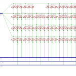
 Before I prepared to cut my 3 strips into 30 smaller ones, and soldered 4 wires to each one, I decided to get a picture of what the final wiring would look like. This was a job for Cadsoft’s Eagle, the defacto-standard for making schematics and PCB layouts. Even though I’m planning on laying out the display by hand, with wires, I felt that having a reference for wiring the matrix would be worthwhile. I built a schematic to show the control layout for the LEDs, as a matrix, which is what the Rainbowduino is designed to drive. I then built a layout based on the schematic that corresponds (roughly, and not to scale) to how I’m planning to arrange the LED strips, although the footprints of all the parts are completely arbitrary. However, the pin layout of the headers on either side match the layout of those on the Rainbowduino, which will make it helpful when it comes time to connect all 120 wires.
Wiring
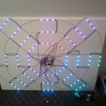
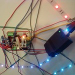
Update, May 2: I’ve now finished wiring the matrix: I attached all of the strips to a piece of foamcore board using their adhesive backing and soldered all of the connections. Everything worked on the first try, and I flashed the code (rainbowduino_v1_0_4) from here. The demo patterns looked amazing, but sadly, shortly after powering it up (before Icould even get a video), something stopped working. Not only were the patterns not being displayed, but I couldn’t get my programmer to connect to the rainbowduino! Luckily, I emailed SeeedStudio, and one of their very helpful employe has promised me that a replacement is already on the way. Hopefully it arrives before the fifth, when I was hoping to set up the display on campus. Until it arrives, and I can replace the defective board on the display, enjoy the only two photos I took while it was working (before I flashed the new firmware onto it).


Final words
Despite the setback with my Rainbowduino, I went ahead with getting the display ready for this weekend, where (hopefully) it will be sitting in a central place, entertaining people with colorful patterns. To do this, I used a large zip-tie to strap the ATX power supply to the back of the piece of foamcore board, and used some more zip ties to position all of the wires out of sight, as well as to securely fasten the two wires running 12V to the display. All in all it looks good, and I’m excited to load some exciting patters onto it once my new control board arrives.
Also, this post is still in progress — check back soon for updates! Apologies for the lack of photos, they should be coming soon.
